| Part | Amount |
| Printed Circuit Board | 1 |
| 500k ohm trim pot | 2 |
| 555 chip | 1 |
| Wire connector blok | 1 |
| Dip switch | 1 |
| 7 pole 2.54 female connector | 1 |
| 1k ohm resistor network | 1 |
| 47nf Capacitor | 2 |
The order of assembly isn’t very important. But care has to be taken not to overheat the small components like the caps and 555 timer
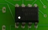
The orientation of the 555 chip is very important. When looking at the circuit side. The chip needs to be inserted orientated as in the picture. The 555 chip is on the opposite side of the board from all the other components.

The orientation of the resistor network can be seen from the component side of the pcb. The box marked with a cross should correspond to the pin of the resistor network marked with a white dot. If you get a the 6 pin version, just clip off the pin opposite the dot.
The finished kit should look like this. In this kit I have chosen to use pin headers instead of the female connector. Both methods can be used.


When connecting the unit to the linistepper take into account the orientation. The outputs given above should correspond to those on the linistepper.
Instead of connecting the kit directly to the linistepper with a cable. Another option is available. Instead of soldering on the trim pots. Potmeters can nicely be put into a housing can be connected by simply soldering them on to the pcb using cables. In that way everything can be neatly packaged…
The kit in its standard form is meant to give a very broad frequency range. This could mean that for your particular application the kit is not running as well as you would like it to. This can be easily fixed. Changing the value of the pot meters or the caps will alter the frequency range.
| f | Hertz |
| R | Ohm |
| C | farads |

Comments: