Parts explanation
for the ultrasonic detection unit(1)
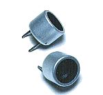 I used the ultrasonic sensor for the air which is made by the Nippon Ceramic company. This sensor separates into the two kinds for the transmitter and the receiver. For the transmitter, it is T40-16 and for the receiver, it is R40-16. T shows the thing for the transmitter and R shows the thing for the receiver. 40 shows the resonant frequency of the ultrasonic.(40KHz) 16 shows the diameter of the sensor. I used the ultrasonic sensor for the air which is made by the Nippon Ceramic company. This sensor separates into the two kinds for the transmitter and the receiver. For the transmitter, it is T40-16 and for the receiver, it is R40-16. T shows the thing for the transmitter and R shows the thing for the receiver. 40 shows the resonant frequency of the ultrasonic.(40KHz) 16 shows the diameter of the sensor.Because the one of the terminal is connected with the case, when grounding, it uses the terminal on the side of the case. 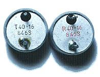 The specification of the ultrasonic sensor is shown below.
As for the detail specification, refer to "Air Transmission Ultrasonic Sensor".  This is the IC which is often used for the timer, the oscillator. This time, the CMOS type is used but the bipolar type is OK. This time, it is used for the oscillation of the transmission timing pulse, the oscillation of the ultrasonic frequency, the gate circuit of the alarm detector and the output circuit.  This IC is the IC of the CMOS which the six inverters are housed in. This IC is mainly used for the drive circuit of the ultrasonic sensor.  This IC is the low noise operational amplifier. It is used for the amplification of the received ultrasonic signal. The low noise type operational amplifier must be used because it does the about 60dB (1000 times) amplification.  This IC is the single power supply-type operational amplifier. This IC is used for the detection of the received signal. The comparator can be used.  As for this IC, the four NAND circuits of 2 inputs are accommodated. It is used to compose SR-FF and to measure the reaching time of the ultrasonic.  The stable +9V can be gotten from +12V to +30V input by this IC. The maximum output current is 100 mA. 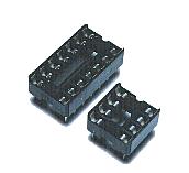 The equipment which was made this time used the sockets for the ICs mounting. It is to adjust in the order. Especially, because IC1 is removed in the adjustment of the ultrasonic frequency, it had better install using the socket.  This is the transistor with the general NPN type for the small signal amplification. It is used for the drive circuit of the relay. If the collector electric current is the equal to or more than 100-mA one with the general NPN-type transistor for the small signal, the other transistor is OK. 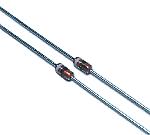 This diode is used to detect the received ultrasonic. The ultrasonic frequency is about 40 KHz, so, the diode with the good high frequency characteristic is used. 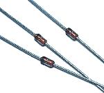 This diode is used for the mask of the transmission pulse and used to prevent from transistor destruction by the back electromotive force of the relay. It is not the special diode. 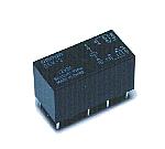 I used the relay to output the alarm outside. I used the relay to output the alarm outside.I used the one that the drive voltage is DC 12 V . There are two sets of points of contact. The specification is shown below respectively. 125V AC : 0.6A 110V DC : 0.6A 30V DC : 2A 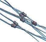 At the circuit this time, the resistors that the permission electric power of the resistor is 1/8 W are used. 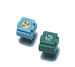 This is the small variable resistor. This is used for the adjustment of the ultrasonic frequency. 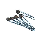 These are the disk-type ceramic capacitors. Because the high frequency characteristic is good, these are used as the coupling capacitors(It cuts the direct current but it lets through the alternating current) of the ultrasonic signal amplification. 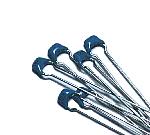 These are used as the bypass capacitors. It is small size but it has the comparatively big capacity(0.1µF). 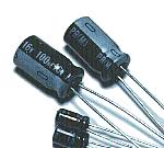 These are used as the ripple filter capacitors of the power circuit. There is polarity. So, Be careful so as not to make a mistake when mounting them. 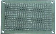 I used the universal printed board. I use two sheets of the boad with 15 holes x 25 holes. 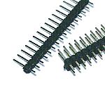 These terminals are used for the wiring with the outside parts such as the power supply wiring. Two lines of the terminals are used to put the ultrasonic sensor. 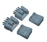 The circuit which was made this time separated the transmitter/receiver part of the ultrasonic and the detector part. The wiring among those printed boards connects through the connector. It is OK even if it connects directly. 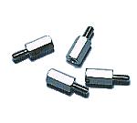 These studs are used to install the equipment in the case. The one which is made of metal because of the grounding is used. Choose the length of stud for the ultrasonic sensor to become case approximately central. This time, I used the one with the 10-mm length. 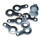 These are used to connect the studs with the ground of the circuit. |
|||||||||||||||||||||