
 Switching regulator Switching regulator
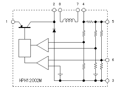
HPH12002M is the IC which has the prime function of the switching regulator such as the switching transistor circuit, the voltage control circuit, the regulator coil, the diode and the heatsink. It works as the regulator by putting the capacitor outside. The output voltage can be changed by the variable resistor.
Two HPH12002M can output twice of electric currents by connecting in parallel.

 Parallel connection of the regulator Parallel connection of the regulator
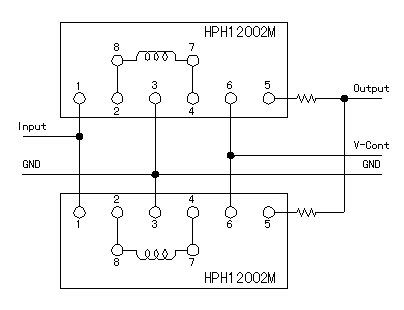
Two HPH12002M can connect in parallel.
You connect the input terminal, the ground terminal, the voltage detection terminal respectively. But, in case of the output terminal, you connect using the resistors to make do the balance of the load.

 Load balance resistors Load balance resistors
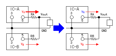
The regulator which used this time is using the one with the equal characteristic. However, the characteristic of the details isn't the same. When connecting the output terminal of both regulators directly, the electric current flows only from the one with the higher output voltage and can not get the equal output.
By connecting the output of the regulator through the resistors, the output from the regulator can be made equal approximately.
With the figure, it supposes that the output of the regulator of IC-A is higher than the output of the regulator of IC-B.
In IC-A, more electric currents flow and the voltage of the both edges of the resistor (RA) rises. Because the output voltage (Vout) is constant, the output voltage of IC-A falls and the output current from IC-A decreases. When the output voltage of IC-A falls below the output voltage of IC-B, the output current flows from IC-B.
The electric power can be equally output approximately from both regulators by above operation.
The load balance becomes good when making the resistance value big but because the electric power is consumed with the resistors, the efficiency becomes bad.

 Voltage adjustment circuit Voltage adjustment circuit
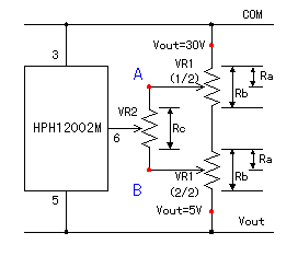
The variable resistor is used for the voltage adjustment. In case of the one variable resistor, because the change range with the voltage is wide(5-30V), to set the voltage in detail is terrible.
It becomes about 0.08V/deg, supposing that the axis of rotation angle of the variable resistor is the 300 degrees. Actually, the about 5-degree adjustment(0.4V) is the limit. To set the 0.1-V unit, it is terrible.
I devised to be able to do the fine control with the voltage.
I combined the twin variable resistor(The two variable resistors are installed in the same axis and the resistance value changes at the same time) and the single variable resistor.
Because the resistance value of each of VR1 changes at the same time, the voltage which is proportional to the turn angle of the axis is applied to the voltage adjustment terminal of the regulator. VR2 can do the voltage adjustment in the narrow range.
The output voltage becomes low when making the voltage adjustment terminal of the regulator the side of the output. It was to 5 V be, being minimum in the measurement. The output voltage becomes high when making the voltage adjustment terminal the side of the grounding. It was to 35 V be in the maximum in the case of the no-load. The maximum voltage depends on the voltage of the input. In case of the no-load, the output voltage becomes the voltage which is the same as the input voltage approximately. Because voltage of the input goes down when the output power is big, the maximum output voltage becomes low.
The range with the voltage which can be adjusted in VR2 can be calculated by the following formula. (Complicated a little)
This formula is the formula in case of the minimum voltage is 5 V and the maximum voltage is 30 V.
 The output voltage when making VR2 the side of the A point The output voltage when making VR2 the side of the A point
 The output voltage when making VR2 the side of the B point The output voltage when making VR2 the side of the B point
In case of Ra=0-ohm(the maximum voltage), Rb=250k-ohm and Rc=20k-ohm, the output voltage when changing VR2 to the A point and the B point becomes the following.
 In case of the A point In case of the A point
 In case of the B point In case of the B point
In case of Ra=250k-ohm(the minimum voltage), Rb=250k-ohm and Rc=20k-ohm, the output voltage when changing VR2 to the A point and the B point becomes the following.
 In case of the A point In case of the A point
 In case of the B point In case of the B point
That is, the output voltage adjustment range by VR2 is about 1.7 V.
Supposing that the turn angle of VR is the 300 degrees, about 18-degree turn changes the 0.1 V voltage. It is possible to do the adjustment easily if being this angle.

I calculated as above mentioned
but the actual voltage change was different from my anticipation.
This is the relation of the voltage adjustment circuit inside the regulator. The change of the output voltage by the change of the resistance value of the variable resistor isn't linear.
The measurement result of the output voltage change by the turn angle of the variable resistor is hereinafter.
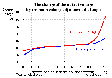
At the center of the main voltage adjustment resistor, little change of the voltage occurs. Therefore, even if I change the fine adjustment resistor, the voltage changes hardly.
Because it was the relation of the inner regulator circuit, I stopped the design of this circuit any more.
In the both edges of the main voltage adjustment resistor, the change percentage with the output voltage is big. In this area, the fine adjustment is effective. So, in case of the practical use, there is no problem.

 Output filter circuit Output filter circuit
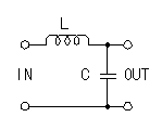
There is a ripple in the output voltage of HPH12002M. The ripple with the output voltage can be made little by putting the filter circuit to the output. The inductance of the coil is the several-ÁH one and is OK. This time, I used the 25-ÁH(Measurement result) toroidal coil which was rolled up by myself.

 Transformer circuit Transformer circuit
It changes AC100 V into AC30 V.
Rectifying AC30 V in the full wave by the diode bridge. The rectified voltage becomes higher than DC30 V. Because the maximum input voltage of the regulator is 40 V, it adjusts with the tap of the transformer so as not to cross this. If connecting with the tap with the low voltage on the side of the secondary, the DC voltage falls.
If the primary(The side of AC100 V) has the tap, the voltage can be adjusted by changing the connection. When connecting with the tap with the high voltage of the primary, the secondary voltage can be dropped.
| Primary | Secondary | DC voltage |
| 100 V | 30 V | 42 V |
| 100 V | 27 V | 38 V |
| 100 V | 24 V | 34 V |
| 110 V | 30 V | 39 V |
| 110 V | 27 V | 35 V |
| 110 V | 24 V | 31 V |
|
The table on the left is the measurement result with the diode bridge output voltage in case of the no-load.
I considered the input voltage change and made the following connection.
Primary : 110 V
Secondary : 27 V |
 |