
 Frequency characteristic of the capacitor Frequency characteristic of the capacitor
Even if the frequency changes, the resistance value of the resistor doesn't change. However, the resistance value of the capacitor is changed by the frequency when applying the alternating current signal to the capacitor. The resistance value of the capacitor is called the capacitive reactance.
In the symbol, Z is used and is as follows.
For example, when applying the alternating current signal of 1KHz to the capacitor which has the 0.01µF capacity, the reactance is as follows.
There is not ideal one in the resistor and the capacitor.
It is little but the resistor has the characteristic of the coil and the characteristic of the capacitor. So, when the frequency becomes high, depending on the kind of the resistor, the characteristic of the coil and the capacitor influences and the resistance value has changed. At the circuit which handles the frequency as this influence becomes the problem, the resistor for the high frequency must be used.
The capacitor has the resistance and the inductance in addition to the capacitance, too. Especially, in case of the capacitor, the one which is doing the structure which rolled up the metallic foil as the pole can not use at the high frequency because there are many inductance.

 Combined resistance by the combination of the capacitor and the resistor (The impedance) Combined resistance by the combination of the capacitor and the resistor (The impedance)
 The series connection The series connection

The combined resistance when connecting the resistors R1 and R2 in series is R1+R2.

The combined resistance when connecting the resistor R1 and the capacitor (Zc) in series isn't demanded in merely addition.
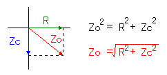 It is because the phase of the voltage which is applied to the capacitor and the electric current which flows through the capacitor shifts by the 90 degrees. The combined resistance must be calculated using the Pythagorean theorem. It is the formula which finds the long side of the right triangle. It is because the phase of the voltage which is applied to the capacitor and the electric current which flows through the capacitor shifts by the 90 degrees. The combined resistance must be calculated using the Pythagorean theorem. It is the formula which finds the long side of the right triangle.
The calculation formula of the actual combined resistance is as follows.

 The parallel connection The parallel connection

The combined resistance when connecting the resistors R1 and R2 in parallel is R1 x R2/(R1+R2).

When connecting the resistor R and the capacitor (Zc) in parallel, it becomes like the left figure.
The calculation formula of the actual combined resistance is as follows.

The troublesome thing was explained but above-mentioned connection is used with the differentiation circuit and the integration circuit.

 Attenuation quantity at the cut-off frequency of the differentiation circuit and the integration circuit Attenuation quantity at the cut-off frequency of the differentiation circuit and the integration circuit
 The differentiation circuit The differentiation circuit
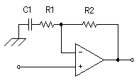
The characteristic of the differentiation circuit is decided by the resistor (R1) and the capacitor (C1).
It is as follows when calculating the impedance by C1 and R1 at the cut-off frequency.
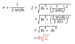 At this time, the gain of the operational amplifier is as follows.
 That is, it becomes about 0.7 times the gain with the frequency which is higher than with the cut-off frequency.
It is as follows when showing
  in the decibel. in the decibel.

 The integration circuit The integration circuit
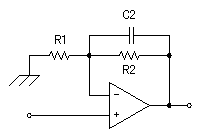
The characteristic of the integration circuit is decided by the resistor (R2) and the capacitor (C2).
It is as follows when calculating the impedance by C2 and R2 at the cut-off frequency.
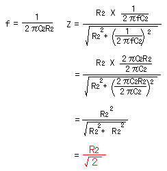 At this time, the gain of the operational amplifier is as follows.
 That is, it becomes about 0.7 times the gain with the frequency which is lower than with the cut-off frequency.
It is as follows when showing
  in the decibel. in the decibel.
 At the cut-off frequency, the gain of the differentiation circuit and the integration circuit falls by 3 dB.
 |