Parts explanation
of the ultraviolet ray exposure equipment (3)
I make the explanation the following about each part of the ultraviolet ray exposure equipment.
[Menu]>[Manufacturing of Original PCB]>[Implement of the PBC making]>[Ultraviolet ray exposure equipment]>[Equipment explanation]

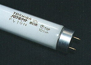
I am using the fluorescence light of the 10 watts.
It is using the marketed one. However, the fluorescence color has some kinds and the time difference may come out little with the exposure of the board to light.

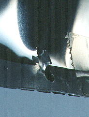
The fixation of the reflection board can scratch the reflection board by making a cut in the underside of the chassis and bending it inside.
It is fixing the four corners with the adhesive tape.

The power supply switch, the LED for the remainder time display, the thumbwheel switch for the time setting and the start switch are installed on the reticular equipment cover.
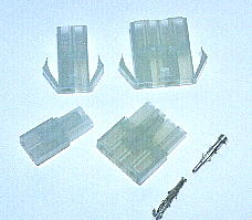
Those connection wires are troublesome when removing the cover. Therefore, make it be possible to detach the wire on the way by putting the connector.
I am using the connector of this type for the AC power supply wire.

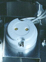
It is the socket to install the fluorescence pipe.
The socket of the fluorescence pipe has some kinds. This time, I am using the type to press with the spring. Think of the way of installing the socket and choose it.