PIC16F84A PIC16F84A
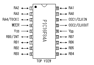
The electric wave which was made with oscillato is controlled by this PIC.
A control code is made with the software of PIC16F84A. The control code can be easily changed if changing software.
It uses RA0 and RA1 for the input to choose a control code and it is using RA4 for the control of the oscillation circuit.
Transistor for high frequency oscillation and high frequency power amplification ( 2SC1906 )
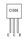
2SC1906 is used for the high-frequency oscillator and the power amplification.
The transistor with high fT (the maximum cutoff frequency) is needed because it handles a high frequency. The fT of 2SC1906 is 600MHz-1000MHz. Because it handles an about 80-MHz frequency at the circuit this time, there is a lot of leeway.
3 terminal regulator ( 78L05 )
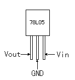
The power of this transmitter is a +9V battery.
3 terminal regulator is used to make the power (+5V) of PIC from +9V power.
A 100mA type is used.
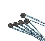
Resonator
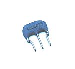
This is the oscillation device to make the clock of PIC. A ceramic vibrator and capacitors are incorporated.
The clock frequency this time is 4 MHz. It is possible to make do the operation of PIC16F84A with the a maximum of 20MHz clock.
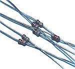
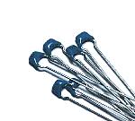
Diode
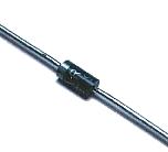
This is the diode to control the input of PIC by the switch operation. This time, I used diodes for the rectification. However, because few flowing electric currents occur, the switching diode (Io=120mA) such as 1S588 and so on can be used.
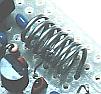
Coil
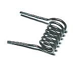
The coil to be using this time is using the one to have wound a tin plating wire with 0.6mm diameter around the stick (the screwdriver) with 4.6mm diameter seven times. I make a tap (the node of the power) at the position of 4.5 turns from the side which connects with the collector.
You can use a coil bobbin with the core, too.
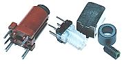
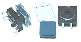
IC socket
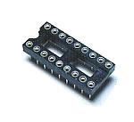
This is an 18 pins socket for PIC16F84A.
I used a round hole type but you can use a board type, too.
Resistor
As for the resistor, all 1/8W are used.
Ceramic capacitor
Ceramic capacitors with good high frequency characteristic are used for the resonance circuit of the oscillator.
Multilayer ceramic capacitor
The unnecessary high frequency which influences circuit operation is bypassed with these capacitors.
This capacitor has a large capacity comparatively with 10000pF but it is small.
Printed board
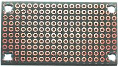
The universal printed board which was cut in the needed size is used.
When handling a high frequency circuit, the length of the wiring influences the operation of the circuit. Because it is, actually, it had better use a printed board.
Stud
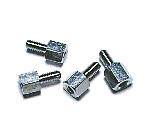
These studs are used to fix a printed board on the case.
Battery
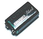
It used a 9V dry battery.
This dry battery is called 006P in Japan. Maybe this dry battery is called as 1604(NEDA) or 6F22(IEC).
Dry battery plug
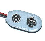
The pole of the 9V dry battery connects with the special plug.
Switch
These switchs combine the power switch and the selection of the control code. These are a non lock type. Only while pushing a switch, the electric wave which was controlled with the code is emitted.
Case
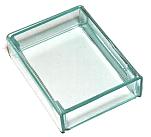
I housed a transmitter in the case which was made by bending acrylic board.
Cushion for battery
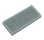
A sponge was used to fix a battery in the case. I used the sponge of 6 mm of thickness.
|