Parts explanation for +30V power supply
 This is the inverter circuit which has the hysteresis characteristic. 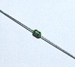 This is the micro coil and the inductance is 18 µH. The permissible current of this coil is obscure. I think that it does from several mA to tens of mA. The size is as the 1/8-W resistor. 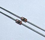 This is the shottky barrier diode for the small electric power. Because the reverse recovery time is short, the shottky barrier diode can do the high-speed switching operation. The diode which was used this time is 1SS108. The reverse direction maximum voltage of this diode is 30 V and the forward direction maximum electric current is 15 mA. 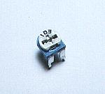 This is a small variable resistor to adjust the frequency of the oscillator. 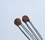 The ceramic capacitor with the small disk type is used. 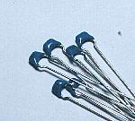 The multilayer ceramic capacitor with the small and comparatively big capacity is used for the capacitor to use with the filter circuit. 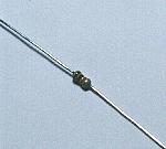 The small resistor of 1/8 W is used. The output current of the power supply this time is about 3 mA even if maximum. So, it is OK with the resistor with the permission electric power of 1/8 W. I2 x R = (0.003)2A x 1000 ohm = 9 mW 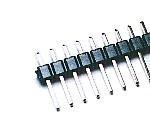 This is the terminal to wire with the circuit outside. It uses according to the necessity. 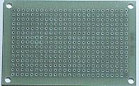 I used the universal printed board. It cuts in the necessary size and it uses. 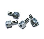 I used the metallic stud to install the printed board in the case. |