T H E S X - D E V H A R D W A R E
5
6 ² Reset, optional for external reset connection, not used by realtime module
SX-TIPS can also be attached to 4-pin header, compatible with Parallax and TransData in-circuit programmers
and emulators. Only pins 1-4 should be used in this case.
Real-time module
Real-time module connected between SX_TIPS debugger/
programmer and target board and powered from the target board.
Four different clock sources can be used ² DIP 14-pin plastic or
metal package oscillator; H&-49/U case or compatible crystal;
ZTT/ZTA series or compatible ceramic oscillator or external clock
source. Please ensure, that jumper on the top of the real-time
module board installed according to the used clock source. Take the
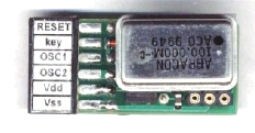
board with jumper on top, 6-pin connector on the left (as on the first
photo). Than check/change jumper position, as described below:
DIP 14-pin oscillator
jumper on the left two pins
External clock
jumper on the left two pins
H&-49/U crystal
jumper on the right two pins
ZTT/ZTA ceramic oscillator
jumper on the right two pins
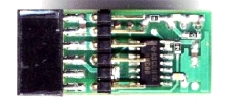
DIP 14-pin oscillator should be installed with the first pin on the right top corner of the board (as on the
photo). Any frequency up to 100 MHz can be used (module can work till 120«150 MHz, however current SX
chips not rated to this frequencies). Please take into account oscillator supply current - typical high-frequency
oscillators usually draw 30«60 mA, this current will be drawn from the target board.
External clock signal should be supplied with short wire on the left bottom receptacle of the DIP14 socket or
to the middle pin of the 3-pin jumper header. Do not forget connect also ground wire (for example, to the right
bottom receptacle), if ground of the external clock source is not the same, as at the target board ground. &MOS
output for the external clock signal recommended, any frequency up to 100 MHz allowed.
H&-49/U or compatible crystal should be installed to the two receptacles on the right bottom of the real-time
module. Only fundamental crystals can be used. On-board generator optimized for high-frequency crystals ²
most fundamental microprocessor-grade crystals from 1 MHz till 100 MHz can be used. Generator supply
current depended from the crystal frequency and for most crystals will be in range 2«30 mA.
ZTT/ZTA or compatible ceramic oscillator can also be used. Both 2-pin and 3-pin (with built-in capacitors)
ceramic oscillators works well with on-board generator in range 1«50 MHz. &eramic oscillator should be
installed to the two receptacles on the right bottom of the real-time module. Generator supply current
depended from the crystal frequency and for most ceramic oscillators will be in range 2«30 mA.

