P R O G R A M M E R
20
Device options
Memory Map ² &onfigured
Memory Size (SX18/28 only).
These
factory-configured
options should not be changed
unless you want to reduce the
configured
amount
of
program memory in the
device.
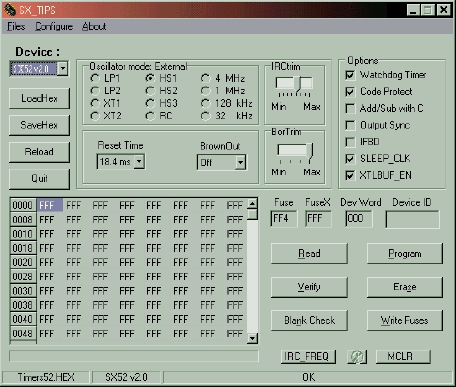
Bor Trim ² Brown Out trim
bits. These bits allow fine tune
of brownout level. Parts are
shipped
from
factory
untrimmed.
IR& Trim ² Internal R&
Oscillator trim bits. These bits
adjust the operation of the
internal R& oscillator to make
it operate within the target
frequency range of 4.0 MHz
(typical) plus or minus 8%.
Parts are shipped from factory untrimmed. To measure current microcontroller frequency, press IR&_FREQ
button. Measured internal R& oscillator frequency will be displayed in the status bar.
value, program target SX and measure resulting frequency.
Oscillator Mode ² This combination of bits sets up the device to operate with a particular type of external
oscillator or sets the divide-by factor for generating the instruction clock from the internal oscillator. Eight
external oscillator options determined as follows:
LP1 ² low-power crystal (32 kHz)
LP2 ² low-power crystal/resonator (32 kHz to 1 MHz)
XT1 ² low power crystal/resonator (32 kHz to 10 MHz)
XT2 ² normal crystal/resonator (1 MHz to 24 MHz)
HS1 ² normal crystal/resonator (1 MHz to 50 MHz)
HS2 ² normal crystal/resonator (1 MHz to 50 MHz)
HS3 ² normal crystal/resonator (1 MHz to 50 MHz)
R& ² external R&, OS&2 is pulled high with a weak pullup, no &LKOUT output
Four nominal instructions rates with internal oscillator determined as 4 MHz, 1 MHz, 128 kHz and 32 kHz.

